
sábado, 20 de diciembre de 2014
sábado, 13 de diciembre de 2014
sábado, 6 de diciembre de 2014
TPs - Final
Estimados,
Para postear los TPs tienen tiempo hasta martes 9 del corriente. Enviando un mail a cursoreparacion2.entrada@blogger.com
Y verificandolo aca en el blog como nueva entrada en la parte superior.
Recuerden leer los TPs del resto y el material de estudio que les dejé por acá el día de ayer. El sábado próximo es el final, recuerden sus libretas y papeles al día.
Saludos
J.R.
Modelo de examen Curso
Modelo de Examen Teórico:
Nombre y apellido:
Fecha:
Por favor indique la respuesta correcta
|
Q.1)
|
Una PC navega lento en Internet principalmente porque:
| |||
A.
|
El PC tiene una placa de video con poca resolución
| |||
B.
|
El PC esta infectado por Spyware que consumen el ancho de banda
| |||
C.
|
Tenemos una conexión muy lenta menor a 56kbits
| |||
D.
|
Los sitios que visitamos tienen muchas imágenes
| |||
E.
|
Hay muchos virus y basura en los mensajes de correo electrónico.
| |||
Q.2)
|
Dos declaraciones que describen una NIC, son:
| |||||
A.
|
Un dispositivo que utiliza ondas de radio para enviar datos de la placa base al disco duro
| |||||
B.
|
Un dispositivo que conecta un PC a una red local inalámbrica
| |||||
C.
|
Un dispositivo que se conecta directamente un PC a una WAN
| |||||
D.
|
Un dispositivo que se conecta el PC a una impresora
| |||||
E.
|
Un dispositivo que conecta un PC a una LAN cableada.
| |||||
Q.3)
|
Tres valores que debe estar configurado para permitir que un PC para conectarse con una red? (Elija 3)
| |
A.
|
Dirección de MAC en el Nic
| |
B.
|
Dirección IP
| |
C.
|
Máscara
| |
D.
|
Puerta de Enlace
| |
E.
|
Direcciones de Correo
| |
Q.4)
|
Qué comando, disponible en Windows 2000 y Windows XP, se mostrará la información de configuración de red de un PC?
| |
A.
|
CONFIG
| |
B.
|
IPCONFIG
| |
C.
|
IFCONFIG
| |
D.
|
WINIPCFG
| |
Q.5)
|
Raúl esta configurando un servidor Exchange para un cliente. Antes de su instalación, el cliente ha pedido los números de puertos que deben ser abiertos en la empresa por cuestiones de seguridad. Usted necesita permitir el correo electrónico SMTP como mecanismo de ejecución, y sólo va a permitir que Outlook Web Access a través de HTTP sobre SSL por lo que es seguro. ¿Cuál de los siguientes puertos son necesarios abrir para la correcta utilización del servidor Exchange?
| |||||
A.
|
Puerto 21
| |||||
B.
|
Puerto 25
| |||||
C.
|
Puerto 80
| |||||
D.
|
Puerto 443
| |||||
E.
|
Puerto 110
| |||||
Q.6)
|
Los usuarios se quejan de que no pueden acceder a recursos de la casa central. Se realizaron Ping a algunos hosts en la sede central y las respuestas son todas infructuosas. ¿Cuál sería el siguiente paso para localizar el problema?
| |||||
A.
|
Utilice la utilidad Trace Route (tracert)
| |||||
B.
|
Reiniciar el router
| |||||
C.
|
Borrar la tabla de enrutamiento
| |||||
D.
|
Cambiar por otro router.
| |||||
Q.7)
|
Según la RFC1918 que direcciones IP son asignadas para redes privadas
¿Cuáles? | |||||
A.
|
10.0.0.0 - 10.255.255.255
| |||||
B.
|
192.168.0.0 - 192.168.255.255
| |||||
C.
|
172.16.0.0 - 172.32.0.0
| |||||
D.
|
172.16.0.0 - 172.31.255.255
| |||||
E.
|
192.169.0.0 - 192.169.255.255
| |||||
Dominio colición
El Sábado, 6 de diciembre, 2014 15:19:16, claudio florentin <clauramon2000@yahoo.com.ar> escribió:
dominio de colisión es un segmento físico de una red de computadores donde es posible que las tramas puedan "colisionar" (interferir) con otros. Estas colisiones se dan particularmente en el protocolo de red Ethernet.
A medida que aumenta el número de nodos que pueden transmitir en un segmento de red, aumentan las posibilidades de que dos de ellos transmitan a la vez. Esta transmisión simultánea ocasiona una interferencia entre las señales de ambos nodos, que se conoce como colisión. Conforme aumenta el número de colisiones disminuye el rendimiento de la red.
Un dominio de colisión puede estar constituido por un solo segmento de cable Ethernet en una Ethernet de medio compartido, o todos los nodos que afluyen a un concentrador Ethernet en una Ethernet de par trenzado, o incluso todos los nodos que afluyen a una red de concentradores y repetidores.
ACL- Hernan Sarlo
ACL (Lista de control de acceso)
By Hernan Sarlo
¿Qué es una ACL?
Una ACL es una colección secuencial de sentencias de permiso o rechazo que se aplican
a direcciones o protocolos de capa superior. Los routers proporcionan capacidades de
filtrado de tráfico a través de las listas de control de acceso (ACL).
Las ACL son listas de instrucciones que se aplican a una interfaz del router. Estas listas indican al router qué tipos de paquetes se deben aceptar y qué tipos de paquetes se deben denegar. La aceptación y rechazo se pueden basar en ciertas especificaciones, como dirección origen, dirección destino y número de puerto. Cualquier tráfico que pasa por la interfaz debe cumplir ciertas condiciones que forman parte de la ACL. Las ACL se pueden crear para todos los protocolos enrutados de red, como IP e IPX, para filtrar los paquetes a medida que pasan por un router. Es necesario definir una ACL para cada protocolo habilitado en una interfaz si desea controlar el flujo de tráfico para esa interfaz. Por ejemplo, si su interfaz de router estuviera configurada para IP, AppleTalk e IPX, sería necesario definir por lo menos tres ACL. Cada ACLs sobre cada interfaz, actúa en un sentido, distinguiendo tanto sentido de entrada como de salida. Se puede definir diferentes ACLs y luego instalarlas sobre los interfaces del router según convenga al administrador de la red.

Razones para el uso de ACLs
Hay muchas razones para crear ACLs. Por ejemplo, las ACL se pueden usar para:
• Limitar el tráfico de red y mejorar el rendimiento de la red. Por ejemplo, las
ACL pueden designar ciertos paquetes para que un router los procese antes de
procesar otro tipo de tráfico, según el protocolo. Esto se denomina colocación en
cola, que asegura que los routers no procesarán paquetes que no son necesarios.
Como resultado, la colocación en cola limita el tráfico de red y reduce la
congestión.
• Brindar control de flujo de tráfico. Por ejemplo, las ACL pueden restringir o
reducir el contenido de las actualizaciones de enrutamiento. Estas restricciones
se usan para limitar la propagación de la información acerca de redes específicas
por toda la red.
• Proporcionar un nivel básico de seguridad para el acceso a la red. Por ejemplo,
las ACL pueden permitir que un host acceda a una parte de la red y evitar que
otro acceda a la misma área. Al Host A se le permite el acceso a la red de
Recursos Humanos, y al Host B se le deniega el acceso a dicha red. Si no se
configuran ACL en su router, todos los paquetes que pasan a través del router
supuestamente tendrían acceso permitido a todas las partes de la red.
• Se debe decidir qué tipos de tráfico se envían o bloquean en las interfaces del
router. Por ejemplo, se puede permitir que se enrute el tráfico de correo
electrónico, pero bloquear al mismo tiempo todo el tráfico de telnet.
Funcionamiento de las ACLs
Una ACL es un grupo de sentencias que define cómo los paquetes:
• Entran a las interfaces de entrada
• Se reenvían a través del router
• Salen de las interfaces de salida del router
El principio del proceso de comunicaciones es el mismo, ya sea que las ACL se usen o no. Cuando un paquete entra en una interfaz, el router verifica si un paquete es enrutable o puenteable. Ahora, el router verifica si la interfaz de entrada tiene una ACL. Si existe, ahora se verifica si el paquete cumple o no las condiciones de la lista. Si el paquete es permitido, entonces se compara con las entradas de la tabla de enrutamiento para determinar la interfaz destino. A continuación, el router verifica si la interfaz destino tiene una ACL. Si no la tiene, el paquete puede ser enviado directamente a la interfaz destino. Las sentencias de la ACL operan en orden secuencial lógico. Si se cumple una condición, el paquete se permite o deniega, y el resto de las sentencias de la ACL no se verifican. Si las sentencias de la ACL no se verifican, se impone una sentencia implícita de "denegar cualquiera". Esto significa que, aunque la sentencia "denegar cualquiera" no se vea explícitamente en la última línea de una ACL, está allí.

Ejemplos de ACL´s
Introducción:
Las listas de acceso (ACLs Access Lists) son filtros que utilizan una numeración
para identificarse:
1-99 son ACLs estándar
100-199 son ACLs extendidas.
Las ACLs estándar tienen la configuración siguiente:
Router(config)# access-list nº permit|deny origen [wild-mask]
y se aplican a los interfaces con:
Router (config-if)# ip access-group nº in|out
siendo in la indicación del tráfico a filtrar que ENTRA por la interfaz del router y out
la indicación para filtrar el tráfico que SALE por la interfaz del router.
Además la wild-mask, indica con 0 el bit a evaluar y con 1 indica que el bit
correspondiente se ignora. Por ejemplo, si quiero indicar un único host 192.13.13.1
especifico: 192.13.13.1 con wild-mask 0.0.0.0 y si quiero especificar toda la red clase
C correspondiente lo indico con 192.13.13.0 y wild-mask 0.0.0.255.
Las ACLs estándar solo pueden filtrar el tráfico por origen nunca por destino.
Las ACLs extendidas tienen la configuración siguiente, donde dependiendo del
protocolo especificado (IP, ICMP, TCP, UDP, ...) tendremos opciones de
configuración diferente, siempre acorde con el protocolo, es decir con TCP podré
utiliza operación de puertos pero con IP no. La sintaxis de las ACLs extendidas es:
Router (config)# access-list nº permit|deny protocolo
origen [wild-mask] [operación] [puerto origen] destino
[wild-mask] [operación] [puerto destino] [established]
La opción de [established] indica que sólo pasarán paquetes TCP con los flags ACK
o RST activados, es decir, que no permite pasar ningún comienzo de conexión con
el flag SYN=1 ACK=0, de inicio de sesión TCP. Podemos forzar así que el
establecimiento de la conexión se realice en el sentido contrario donde está
establecida la lista de acceso. 2
Como operación se suele usar eq que significa igual (equal)
Las ACLs se aplican a los interfaces con la siguiente sintaxis, siendo "out" la opción
por defecto:
Router (config-if)# ip access-group nº in|out
Importante:
• Es conveniente que desactives el cortafuegos de tu ordenador antes de
empezar esta práctica:
service iptables stop
• Recuerda que solo se pueden definir 2 ACLs por cada interfaz. Una de
entrada y otra de salida
Mascara de Wildcard
Una máscara wildcard es una cantidad de 32 bits que se divide en cuatro octetos, en la
que cada octeto contiene 8 bits. Un bit de máscara wildcard de 0 significa "verificar el
valor de bit correspondiente" y un bit 1 de una máscara wildcard significa "no
verificar (ignorar) el valor de bit correspondiente". Una máscara wildcard se
compara con una dirección IP. Los números uno y cero se usan para identificar cómo
tratar los bits de la dirección IP correspondientes. Las ACL usan máscaras wildcard para
identificar una sola o múltiples direcciones para las pruebas de aprobar o rechazar.
Aunque ambas son cantidades de 32 bits, las máscaras wildcard y las máscaras de
subred IP operan de manera diferente.
Digamos que desea verificar una dirección IP para verificar la existencia de subredes
que se pueden permitir o denegar. Supongamos que la dirección IP es una dirección
Clase B (es decir, que los primeros dos octetos son el número de red) con 8 bits de
división en subredes (el tercer octeto es para las subredes). Es necesario usar bits de
máscara wildcard IP para permitir todos los paquetes desde cualquier host en las
subredes 172.30.16.0 a 172.30.31.0. La figura muestra un ejemplo de cómo usar la
máscara wildcard para hacer esto. Para empezar, la máscara wildcard verifica los
primeros dos octetos (172.30), utilizando los bits de cero correspondientes en la máscara
wildcard. Como no interesan las direcciones de host individuales (un identificador de
host no tiene .00 al final de la dirección), la máscara wildcard ignora el octeto final,
utilizando los bits unos correspondientes en la máscara wildcard.

En el tercer octeto, la máscara wildcard es 15 (00001111), y la dirección IP es 16
(00010000). Los primeros cuatro ceros en la máscara wildcard indican al router que
debe comparar los primeros cuatro bits de la dirección IP (0001). Como los últimos
cuatro bits se ignoran, todos los números dentro del intervalo de 16 (00010000) a 31
(00011111) coinciden porque comienzan con el patrón 0001. Para los cuatro bits finales
(menos significativos) en este octeto, la máscara wildcard ignora el valor porque en
estas posiciones, el valor de la dirección puede ser cero o uno binarios, y los bits
wildcard correspondientes son unos. En este ejemplo, la dirección 172.30.16.0 con la
máscara wildcard 0.0.15.255 coincide con las subredes 172.30.16.0 a 172.30.31.0. La
máscara wildcard no coincide con ninguna otra subred.
Trabajar con representaciones decimales de bits wildcard binarios puede ser una tarea
muy tediosa. Para los usos más comunes de las máscaras wildcard, se pueden usar
abreviaturas. Estas abreviaturas reducen la cantidad de cosas que hay que escribir
cuando se configuran condiciones de prueba de direcciones. Si especificamos que
cualquiera cumple la sentencia pondríamos como dirección IP 0.0.0.0 y de máscara todo
1's para que se ignore (255.255.255.255).
ACL Estándar
Las ACL estándar verifican solo la dirección origen de los paquetes que se deben
enrutar. Se deben usar las ACL estándar cuando se desea bloquear todo el tráfico de una
red, permitir todo el tráfico desde una red específica o denegar conjuntos de protocolo.
El resultado permite o deniega el resultado para todo un conjunto de protocolos, según
las direcciones de red, subred y host. Las ACL estándar, aunque son más fáciles de
crear, proporcionan menor control sobre el tráfico de red.
ACL Extendida
Las ACL extendidas verifican las direcciones origen y destino de los paquetes. También
pueden verificar protocolos, números de puerto y otros parámetros específicos. Esto
ofrece mayor flexibilidad para describir las verificaciones que debe realizar la ACL.
Las ACL extendidas se usan con mayor frecuencia para verificar condiciones porque ofrecen una mayor cantidad de opciones de control que las ACL estándar. Se puede usar una ACL extendida cuando se desea permitir el tráfico de la Web pero denegar el Protocolo de transferencia de archivos (FTP) o Telnet desde las redes que no pertenecen a la empresa. Como las ACL extendidas pueden bloquear el tráfico según la dirección destino, se pueden ubicar cerca del origen, lo que ayuda a reducir el tráfico de red. Algunos de los números de puerto más comunes aparecen en la tabla. :

Material de estudio
Material de estudio – Curso supervisión de redes 2014
Unidad 1: Windows Server.
Introducción a los sistemas operativos en red. Windows Server. Introducción al sistema operativo, versiones. Instalación de Windows Server. Actualización del sistema operativo (Release). Aplicaciones de un servidor. Instalación de roles y atributos del servidor Windows.
¿Qué son los roles, servicios de rol y características?
En esta sección, se definen los términos role, role service y feature en el ámbito de Windows Server 2008 R2.
Roles
Un rol de servidor es un conjunto de programas de software que, una vez que se instalan y configuran correctamente, permiten a un equipo realizar una función específica para varios usuarios u otros equipos de una red. En términos generales, los roles comparten las siguientes características.
• Describen la función, la finalidad o el uso principal de un equipo. Un equipo en concreto puede estar dedicado a desempeñar un solo rol que se use intensamente en la empresa o puede desempeñar varios roles si cada uno de ellos se usa con menos intensidad.
• Proporcionan a los usuarios de una organización acceso a los recursos administrados por otros equipos, como sitios web, impresoras o archivos almacenados en distintos equipos.
• Suelen incluir sus propias bases de datos, que pueden poner en cola las solicitudes de usuarios o equipos, o pueden registrar información relacionada con el rol acerca de los usuarios y equipos de la red. Por ejemplo, Servicios de dominio de Active Directory incluye una base de datos para almacenar los nombres y las relaciones jerárquicas de todos los equipos de una red.
• Tan pronto como se han instalado y configurado correctamente, los roles funcionan automáticamente. Esto permite a los equipos donde están instalados realizar las tareas necesarias con un nivel de supervisión o comandos de usuario limitados.
Servicios de rol
Los servicios de rol son programas de software que proporcionan funcionalidad de un rol. Al instalar un rol, puede elegir los servicios de rol que el rol proporcionará a otros usuarios y equipos de la empresa. Algunos roles, como Servidor DNS, tienen una sola finalidad y, por lo tanto, no tienen servicios de rol disponibles. Otros roles, como Servicios de Escritorio remoto, tienen varios servicios de rol que pueden instalarse, en función de las necesidades de los equipos remotos de la empresa.
Un rol puede considerarse como una agrupación de servicios de rol complementarios y estrechamente relacionados, para los cuales, en la mayoría de los casos, la instalación del rol implica la instalación de uno o varios de sus servicios de rol.
Características
Las características son programas de software que, aunque no forman parte directamente de los roles, pueden complementar o aumentar su funcionalidad, o mejorar la funcionalidad del servidor, independientemente de los roles que estén instalados. Por ejemplo, la característica Clúster de conmutación por error aumenta la funcionalidad de otros roles, como Servicios de archivo y Servidor DHCP, ya que permite a estos roles unirse a clústeres de servidores para obtener una mayor redundancia y rendimiento. Cliente Telnet es otra característica que le permite comunicarse de forma remota con un servidor telnet a través de una conexión red, una funcionalidad que mejora las opciones de comunicación del servidor.
Unidad 2: Redes.
Definición, tipos de redes, topologías. Introducción a los dispositivos de Networking. Software Cliente – Servidor. Administración centralizada de las redes. El rol del supervisor de redes: Relevamientos, funciones y alcance. Red privada virtual. (VPN). Recursos compartidos.
NIC
Una tarjeta de red, tarjeta de interfaz de red o adaptador de red es un periférico que permite la comunicación con aparatos conectados entre sí y también permite compartir recursos entre dos o más computadoras (discos duros, CD-ROM, impresoras, etc). A las tarjetas de red también se les llama NIC (por network interface card; en español "tarjeta de interfaz de red" o TIR). Hay diversos tipos de adaptadores en función del tipo de cableado o arquitectura que se utilice en la red (coaxial fino, coaxial grueso, Token Ring, etc.), pero actualmente el más común es del tipo Ethernet utilizando una interfaz o conector RJ-45.
Direcciones IP
Las direcciones IPv4 se expresan por un número binario de 32 bits, permitiendo un espacio de direcciones de hasta 4.294.967.296 (232) direcciones posibles. Las direcciones IP se pueden expresar como números de notación decimal: se dividen los 32 bits de la dirección en cuatro octetos. El valor decimal de cada octeto está comprendido en el intervalo de 0 a 255 [el número binario de 8 bits más alto es 11111111 y esos bits, de derecha a izquierda, tienen valores decimales de 1, 2, 4, 8, 16, 32, 64 y 128, lo que suma 255].
En la expresión de direcciones IPv4 en decimal se separa cada octeto por un carácter único ".". Cada uno de estos octetos puede estar comprendido entre 0 y 255.
Ejemplo de representación de dirección IPv4: 10.128.1.253
Ipconfig: Es una utilidad de línea de comandos que muestra la configuración de red actual de un ordenador local (dirección IP, máscara de red, puerta de enlace asignada a la tarjeta de red, etc ), así como controlar el servicio Windows que actúa como cliente DHCP.
* ipconfig: muestra información
* ipconfig /all: muestra información detallada
* ipconfig /renew: renueva todos los adaptadores * ipconfig /release : libera todas las conexiones
Capa 4
Puertos de comunicación
20/tcp FTP File Transfer Protocol (Protocolo de Transferencia de Ficheros) - datos
21/tcp FTP File Transfer Protocol (Protocolo de Transferencia de Ficheros) - control
22/tcp SSH, scp, SFTP
23/tcp Telnet manejo remoto de equipo, inseguro
25/tcp SMTP Simple Mail Transfer Protocol (Protocolo Simple de Transferencia de Correo)
37/tcp time (comando)
43/betocp nicname
53/udp DNS Domain Name System (Sistema de Nombres de Dominio), por ejemplo BIND9
67/udp BOOTP BootStrap Protocol (Server), también usado por DHCP
68/udp BOOTP BootStrap Protocol (Client), también usado por DHCP
69/udp TFTP Trivial File Transfer Protocol (Protocolo Trivial de Transferencia de Ficheros)
70/tcp Gopher
79/tcp Finger
80/tcp HTTP HyperText Transfer Protocol (Protocolo de Transferencia de HiperTexto) (WWW)
88/tcp Kerberos Agente de autenticación
110/tcp POP3 Post Office Protocol (E-mail)
111/tcp sunrpc
113/tcp ident (auth) antiguo sistema de identificación
119/tcp NNTP usado en los grupos de noticias de usenet
123/udp NTP Protocolo de sincronización de tiempo
135/tcp epmap
137/tcp NetBIOS Servicio de nombres
138/tcp NetBIOS Servicio de envío de datagramas
139/tcp NetBIOS Servicio de sesiones
143/tcp IMAP4 Internet Message Access Protocol (E-mail)
161/udp SNMP Simple Network Management Protocol
162/tcp SNMP-trap
177/tcp XDMCP Protocolo de gestión de displays en X11
389/tcp LDAP Protocolo de acceso ligero a Bases de Datos
443/tcp HTTPS/SSL usado para la transferencia segura de páginas web
Mascara de Subred
La máscara de red o redes es una combinación de bits que sirve para delimitar el ámbito de una red de ordenadores.1 Su función es indicar a los dispositivos qué parte de la dirección IP es el número de la red, incluyendo la subred, y qué parte es la correspondiente al host.
Puerta de enlace predeterminada
Una puerta de enlace predeterminada es un dispositivo o una computadora que sirve como enlace entre dos redes informáticas, es decir, es el dispositivo que conecta y dirige el tráfico de datos entre dos redes o más. Generalmente en las casas u oficinas, ese dispositivo es el router y Cable-Modem o DSL-Modem que conecta la red local de la casa (LAN) con Internet (WAN).
Cableado Horizontal
Unidad 3: Active Directory (Directorio Activo).
Perfiles móviles de red. Definición. DNS y DHCP. Elementos del Active Directory. Definición y diferenciación de Bosque, Árbol y Dominio. Controlador de Dominios: Función y aplicación. Creación de Dominio y unión de la PC al Dominio.
Administración de Grupos y Usuarios
Unidades Organizacionales (OU): Aplicación y función. Usuarios y Grupos de usuarios: Alta, baja y modificación. Contraseñas: Políticas de seguridad, reasignación y desbloqueo de usuarios.
Introducción a Active Directory
La seguridad se integra con AD DS a través de la autenticación de inicio de sesión y el control de acceso a los recursos del directorio. Con un solo inicio de sesión de red, los administradores pueden administrar los datos de directorio y la organización a través de la red. Los usuarios de red autorizados también pueden usar un inicio de sesión de red único para tener acceso a cualquier punto de la red. La administración basada en directiva facilita la administración de incluso las redes más complejas.
Algunas características adicionales de AD DS son:
Un conjunto de reglas, el esquema, que define las clases de objetos y atributos incluidos en el directorio, las restricciones y límites de las instancias de estos objetos y el formato de sus nombres.
Un catálogo global que contiene información acerca de todos los objetos del directorio. Los usuarios y los administradores pueden usar el catálogo global para buscar información del directorio con independencia del dominio en que el directorio tiene los datos.
Un mecanismo de consulta e índice para poder publicar los objetos y sus propiedades, y buscar por usuarios o aplicaciones de red.
Un servicio de replicación que distribuye los datos de directorio en una red. Todos los controladores de dominio de escritura de un dominio participan en la replicación y contienen una copia completa de toda la información de directorio del dominio. Cualquier cambio en los datos del directorio se replica en todos los controladores de dominio del dominio.
Unidad 4: Introducción a Linux.
Historia, desde Unix a Linux. GNU (sistema operativo similar a Unix). Distribución Linux. Comandos comunes.
Zentyal: Configuración Zentyal. Servidor de red unificada de código abierto. Modos de servidor Zentyal, como Controlador de Dominios o como Controlador de Dominio adicional.
Zentyal: servidor Linux para pymes
Zentyal se desarrolló con el objetivo de acercar Linux a las pymes y permitirles aprovechar todo su potencial como servidor de empresa. Es la alternativa en código abierto a los productos de Microsoft para infraestructura TIC en las pymes (Windows Small Business Server, Windows Server, Microsoft Exchange, Microsoft Forefront...) y está basado en la popular distribución Ubuntu. Zentyal permite a profesionales TIC administrar todos los servicios de una red informática, tales como el acceso a Internet, la seguridad de la red, la compartición de recursos, la infraestructura de la red o las comunicaciones, de forma sencilla y a través de una única plataforma.
Durante su desarrollo se hizo un especial énfasis en la usabilidad, creando una interfaz intuitiva que incluye únicamente aquellas funcionalidades de uso más frecuente, aunque también dispone de los medios necesarios para realizar toda clase de configuraciones avanzadas. Otra de las características importantes de Zentyal es que todas sus funcionalidades están estrechamente integradas entre sí, automatizando la mayoría de las tareas y ahorrando tiempo en la administración de sistemas.
Linux en la empresa y en el hogar
Cuál es la ventaja de utilizar Linux en la empresa: el ahorro en los costes de licencias. Cualquier organización determinada que utilice Linux en su infraestructura informática ahorra mucho dinero en licencias de software.
Para esto hay dos tipos de distribuciones Linux; las del tipo empresarial ofrecidas por empresas como Red Hat y Novell (SUSE Enterprise) que si cobran una cuota de licenciamiento, pero no por desarrollo del software, sino por servicios de soporte y mantenimiento. Y también se encuentran las del tipo open, que son 100% gratuitas que se ofrecen con soporte bajo las comunidades de usuarios de dichas distribuciones. Estas últimas se utilizan en la mayoría de hogares con sistemas Linux.
Comandos Básicos de Linux
Cat: Cat (de concatenar), es una maravillosa utilidad que nos permite visualizar el contenido de un archivo de texto sin la necesidad de un editor. Para utilizarlo solo debemos mencionarlo junto al archivo que deseamos visualizar: $ cat prueba.txt
Ls: Ls (de listar), permite listar el contenido de un directorio o fichero. La sintaxis es:
$ ls /home/directorio
El comando ls tiene varias opciones que permiten organizar la salida, lo que resulta particularmente útil cuando es muy grande. Por ejemplo, puedes usar -a para mostrar los archivos ocultos y -l para mostrar los usuarios, permisos y la fecha de los archivos. Así como para todos los comandos Linux, estas opciones pueden combinarse, terminando en algo como: $ ls -la /home/directorio
Cd: Cd (de change directory o cambiar directorio), es como su nombre lo indica el comando que necesitarás para acceder a una ruta distinta de la que te encuentras. Por ejemplo, si estas en el directorio /home y deseas acceder a /home/ejercicios, seria: $ cd /home/ejercicios
Si estás en /home/ejercicios y deseas subir un nivel (es decir ir al directorio /home), ejecutas:
$ cd ..
Touch: Touch crea un archivo vacío, si el archivo existe actualiza la hora de modificación. Para crear el archivo prueba1.txt en /home, seria: $ touch /home/prueba1.txt
Mkdir: Mkdir (de make directory o crear directorio), crea un directorio nuevo tomando en cuenta la ubicación actual. Por ejemplo, si estas en /home y deseas crear el directorio ejercicios, sería:
$ mkdir /home/ejercicios
Mkdir tiene una opción bastante útil que permite crear un árbol de directorios completo que no existe. Para eso usamos la opción –p : $ mkdir -p /home/ejercicios/prueba/uno/dos/tres
Cp: Cp (de copy o copiar), copia un archivo o directorio origen a un archivo o directorio destino. Por ejemplo, para copiar el archivo prueba.txt ubicado en /home a un directorio de respaldo, podemos usar: $ cp /home/prueba.txt /home/respaldo/prueba.txt
En la sintaxis siempre se especifica primero el origen y luego el destino. Si indicamos un nombre de destino diferente, cp copiará el archivo o directorio con el nuevo nombre. El comando también cuenta con la opción -r que copia no sólo el directorio especificado sino todos sus directorios internos de forma recursiva. Suponiendo que deseamos hacer una copia del directorio /home/ejercicios que a su vez tiene las carpetas ejercicio1 y ejercicio2 en su interior, en lugar de ejecutar un comando para cada carpeta, ejecutamos: $ cp -r /home/ejercicios /home/respaldos/
Mv: Mv (de move o mover), mueve un archivo a una ruta específica, y a diferencia de cp, lo elimina del origen finalizada la operación. Por ejemplo: $ mv /home/prueba.txt /home/respaldos/prueba2.txt
Al igual que cp, en la sintaxis se especifica primero el origen y luego el destino. Si indicamos un nombre de destino diferente, mv moverá el archivo o directorio con el nuevo nombre.
Rm: Rm (de remove o remover), es el comando necesario para borrar un archivo o directorio. Para borrar el archivo prueba.txt ubicado en /home, ejecutamos: $ rm /home/prueba.txt
Este comando también presenta varias opciones. La opción -r borra todos los archivos y directorios de forma recursiva. Por otra parte, -f borra todo sin pedir confirmación. Estas opciones pueden combinarse causando un borrado recursivo y sin confirmación del directorio que se especifique. Para realizar esto en el directorio respaldos ubicado en el /home, usamos: $ rm -fr /home/respaldos
Este comando es muy peligroso, por lo tanto es importante que nos documentemos bien acerca de los efectos de estas opciones en nuestro sistema para así evitar consecuencias nefastas.
Pwd: Pwd (de print working directory o imprimir directorio de trabajo), es un conveniente comando que imprime nuestra ruta o ubicación al momento de ejecutarlo, así evitamos perdernos si estamos trabajando con múltiples directorios y carpetas. Su sintaxis seria: $ pwd
Clear: Clear (de limpiar), es un sencillo comando que limpiara nuestra terminal por completo dejándola como recién abierta. Para ello ejecutamos: $ clear
Man: muestra una documentación completa de todos los comandos. Para clear, por ejemplo:
$ man clear
Unidad 5: Políticas de seguridad del dominio.
Definición de política de seguridad en el dominio: Alcance, superposición. Creación, modificación, eliminación de políticas y asignación a usuarios y grupos.
Unidad 6: Administración y supervisión de cuota de disco
Definición de cuota de disco. Recursos compartidos: Usos y utilidades. Asignación de cuota de disco a los usuarios del dominio. Asignación por grupos.
Cuota de disco
Puede crear una cuota máxima o una cuota de advertencia:
Una cuota máxima impide a los usuarios guardar archivos una vez alcanzado el límite de espacio y genera notificaciones cuando el volumen de datos llega al umbral configurado.
La cuota de advertencia no impone un límite de cuota, pero genera todas las notificaciones configuradas.
Para determinar qué sucede cuando la cuota se acerca al límite, puede configurar umbrales de notificación. Para cada umbral que defina, puede enviar notificaciones por correo electrónico, registrar un evento, ejecutar un comando o script, o generar informes de almacenamiento. Por ejemplo, es posible que desee enviar una notificación al administrador y al usuario que guardó el archivo cuando una carpeta alcance el 85 por ciento del límite de su cuota, y enviar otra notificación cuando se alcance el límite de la cuota. En algunos casos, podría desear ejecutar un script que aumente el límite de la cuota automáticamente cuando se alcance un umbral.
Al crear una cuota en un volumen o una carpeta, puede basar la cuota en una plantilla de cuota o usar propiedades personalizadas. Es recomendable que, siempre que sea posible, base una cuota en una plantilla de cuota. Una plantilla de cuota se puede volver a usar para crear cuotas adicionales y simplifica el mantenimiento continuo de la cuota.
El Administrador de recursos del servidor de archivos también puede generar cuotas automáticamente. Al configurar una cuota automática, puede aplicar una plantilla de cuota a un volumen o una carpeta principal. Se crea una cuota basada en la plantilla para cada una de las subcarpetas existentes y se genera una cuota automáticamente para cada subcarpeta nueva que se cree.
Javier A. Rodriguez
sábado, 29 de noviembre de 2014


viernes, 28 de noviembre de 2014
Para leer!! FINAL DE REDES!!
Basic TCP/IP networking reference guide
Introduction
This reference guide will discuss the basics of TCP/IP networking. Although intended for an audience of Linux users and administrators, the contents of this will apply equally to other operating systems or networking devices. A future tutorial will provide the specific commands and files which provide the configuration on Linux systems.
Although there are other types of network this guide will only cover TCP/IP networking. With the success of the Internet this is the dominant protocol in use almost exclusively today.
This is primarily aimed at the current IP Version 4, although an introduction to IP Version 6 is included. A shortage of remaining IPV4 addresses is encouraging a more agressive push towards IPV6 over the next few years.
TCP/IP Networking
TCP/IP is an abbreviation for Transmission Control Protocol / Internet Protocol. It is a set of protocols that define how two or more computers can communicate with each other. The protocol is effectively a set of rules that describe how the data is passed between the computers. It is an open standard so can be implemented on any computer with the appropriate physical attributes. Within the TCP/IP networking protocol there are lots more protocols. These provide different functionality important to the exchange of data over the networks. These can be integral to the operation of the networking, such as the Domain Name System or could be an application that uses the network such as E-mail (both of these are discussed in further detail later).
Another related protocol is UDP (User Datagram Protocol) which also runs on top of the IP (Internet Protocol). The difference between TCP and UDP is that TCP is connection based protocol whereas UDP is connectionless. In other words when TCP is being used there is a session setup between the hosts and the transfer is guaranteed. For UDP each data packet is sent but there is no checking that it has been received, or anyway of resending within the network layers. An application can run on top of UDP and implement it's own checking that each packet is received, but that is not the same as leaving it to the networking stack to implement.
A common way of comparing these is to liken TCP to the telephone system and UDP to the postal service. With the telephone when you establish a connection with the other person, you know for certain that the user receives the message. If you were disconnected during the telephone conversation then you would know about it and be able to phone the other person again. With the postal system after you post the letter then you do not know for certain whether or not the mail will be received. After you have posted the letter it could be lost or destroyed on it's way to it's destination. Or if the person has moved house they may never receive the letter.
At first it may sound that there is no reason to choose UDP over TCP after all if you can have the extra reassurance then why would you care about UDP. The reason for this is that there is a lot of overhead involved in TCP. For each data packet being sent a confirmation has to be generated and even if there is no data being sent there will often be some kind of keep alive signal. Whereas for some less important data you may just want to send and forget it with the hope it will reach the other end. It's also possible for the sesssion to be handled higher up the networking stack (but I'm getting ahead of myself here).
OSI Model
Networking protocols are often described relating to the OSI model. This is a model to describe the different networking functionality by the Open Standards Institute. The OSI model splits the different functions of networking into different layers. By describing the networking protocols in layers it allows the layer to be changed without affecting other layers. For example when using a different physical connections (e.g. fibre rather than copper), then different signals need to be sent over the cable, but as long as it interacts in the same way with the layers above it then it can still function.
The networking models are particularly useful in that it allows the protocol to be implemented on any system. Allowing UNIX computers to talk as a peer with windows computers or mainframes.
OSI 7-Layer Model
| 7 | Application |
| 6 | Presentation |
| 5 | Session |
| 4 | Transport |
| 3 | Network |
| 2 | Data link |
| 1 | Physical |
Figure 1: OSI 7-Layer Model
The above diagram shows the 7 layer model. Starting from the bottom the function of the layers is as follows:
Physical Layer - describes the media over which the data travels. For instance this describes the voltage of a 1 or 0 signal across a copper wire.
Data Link Layer - describes the means by which the bits are carried across the physical layer. For example this can describe how the start and end of a data stream is indicated.
Network Layer - this layer handles the routing of data through a network. As an example this describes how routing can happen based upon the address of the computers.
Transport Layer and Session Layer - the transport and session layers provide end-to-end session integrity. This includes keep alives to ensure the connection is maintained.
Presentation Layer and Application Layer - These provide the interface to the application. For example this may include the use of the nslookup command to convert a hostname into an IP address.
Whilst the TCP/IP protocol does not exactly match the OSI 7 layer model it can be approximately mapped across onto it. The following diagram shows the TCP/IP stack compared with the OSI 7 layer model.
| OSI model | TCP/IP stack | |
|---|---|---|
| 7 | Application | Application |
| 6 | Presentation | |
| 5 | Session | TCP or UDP |
| 4 | Transport | |
| 3 | Network | IP |
| 2 | Data link | Network interface |
| 1 | Physical | Physical |
Figure 2: TCP/IP Stack Alongside the OSI 7 Layer Model
This model shows how the TCP/IP protocols are mapped onto the 7-layer model. Note that the application and presentation layers have been merged and that the session and transport layers have been merged. The distinction between these layers are not needed in the TCP/IP model. There is an exception in the NFS application in that it sits on top of the SUN RPC protocol which functions as a presentation layer, however for most purposes they are considered as a single layer. Also the borders between the layers are not as rigidly defined in the TCP/IP as in the OSI model and the functions are not neccessarily a direct match between the OSI model.
Knowing the layers of the network model can however be useful when trying to pin down a certain problem. If you can determine that connectivity is working at a certain level within the stack then you can restrict future investigations to the remaining areas.
More about TCP/IP
TCP/IP was originally developed for universities and the military to exchange ideas and files. The development of TCP/IP is initiated by the Internet Architecture Board (IAB), and the development of standards is handled by the Internet Engineering Task Force (IETF). The documents produced by the IAB are called Request For Comments (RFC) which describe the protocols and relevant information useful for the implementation. Anyone can submit a document as an RFC which are reviewed before being published as official RFC's. After an RFC is published and assigned an RFC number is its never revised under the same number. Instead a new RFC must be created which supersedes the previous version.
IP Addressing Scheme
An important part of all networking protocols is the addressing scheme. Without being able to locate the individual machines (or hosts as they are called) then it would not be possible for any communication between the hosts. There will be more than one addressing scheme in use but the most important of these is the Internet Protocol (referred to as IP), this is significant as it provides the addressing for each end of the connection. The other addressing schemes are effectively hidden from the user at layers two or below and are automatically handled by the networking hardware. The current version of IP is called IP version 4 but will be replaced by IPV6 in future. When I refer to IP it refers to version 4 unless otherwise specified.
The addresses used in the Internet Protocl consist of four octets and is 32 bits long. The address is stored in a format known as dotted decimal.
ie.xxx.xxx.xxx.xxx
where xxx is a number between 0 and 255.
So an example IP address may be: 192.168.3.27
Most users however would not actually need to use the IP address. Instead they would refer to the computer using it's host name. The IP address is obtained from the host name using the "Domain Name System" (DNS). There is no actual relationship between the hostname and the IP address instead this uses a lookup table. The Domain Name Service will be discussed later.
The IP addressing scheme provides 232 possible addresses, which could potentially have over 4.2 thousand million individual addresses. The problem with this however is that trying to locate each one of those addresses individual over the Internet would be an enormous task. So instead the address is split into a network and a host portion. The idea being that different organisations can be assigned a network which can have between 256 and 16.7 million addresses available for hosts. The address range now allows up to 3.7 thousand million hosts on 2.1 million networks.
To accommodate for different sized organisations which require a different number of host addresses, the addresses are split into different network classes. There are 5 different classes however only 3 are commonly used.
Class A - These are for large organisations. The network portion is 8 bits long and begins with binary 0. There are 126 possible networks each with up to 16.7 million hosts.
Class B - These are for medium sized organisations. The network portion is 16 bits long and starts with binary 10. There are 16 thousand networks each with up to 65 thousand hosts. In reality the definition of a medium sized organisation would be a very large company
Class C - These are for smaller organisations. The network portion is 24 bits long and begins with binary 110. There are 200 thousand possible networks each with up to 254 hosts. In reality even these are quite large, so are often split further (see later).
Class D - These are allocated for multicast although are rarely used. The addresses begin with binary 1110.
Class E - These are experimental. The addresses begin with binary 1111.
IP Address class ranges
| Class A | 0.hhh.hhh.hhh | to | 127.hhh.hhh.hhh |
| Class B | 128.nnn.hhh.hhh | to | 191.nnn.hhh.hhh |
| Class C | 192.nnn.nnn.hhh | to | 223.nnn.nnn.hhh |
| Class D | 224.xxx.xxx.xxx | to | 239.xxx.xxx.xxx |
| Class E | 240.xxx.xxx.xxx | to | 255.xxx.xxx.xxx |
Figure 3: IP address class ranges
In the above table the nnn represent the network portion of the address and the hhh represent the host portion of the address.
The observant, mathematically minded my have noticed that some of the numbers mentioned earlier appear to be incorrect. Some of these are through rounding down, but others are due to certain addresses being reserved for other uses.
Reserved Addresses
| 127.0.0.1 | Refers to localhost |
| All host bits binary 0s | Refer to the network |
| All host bits binary 1s | Broadcast address - send to all addresses |
Private Address Ranges (defined in RFC 1918)
| Class A | 10.0.0.0 | to | 10.255.255.255 |
| Class B | 172.16.0.0 | to | 172.31.255.255 |
| Class C | 192.168.0.0 | to | 192.168.255.255 |
The private address ranges are for use internally within an organisation. They cannot be used on the Internet. To provide Internet access for a host with a private address range the communications have to go through a NAT (Network Address Translation). This is one way that the number of available IP addresses can be preserved.
Apart from the private address ranges all other IP addresses need to be registered with the InterNIC before they can be used.
Subnet Masks
The biggest problem with the IP addressing scheme is that it is rapidly running out of free addresses. The long term solution is to move from IP version 4 to IP version 6 which will provide 340,282,366,920,938,463,463,374,607,431,768,211,456 separate addresses. This should provide for all the Internet will ever need, even if every electronic device is given its own IP address. In the meantime a method was needed to make better use of the addresses available under the IP version 4 scheme.
One of the problems with the current addressing is that the addresses are given away in large chunks. Subnetting allows these large chunks of addresses to be further split into a further network and host component. This new network component is called the subnet.
The following shows how a class B network address could effectively split into 254 separate virtual class C networks:
nnn.nnn.sss.hhh
nnn = network portion of the address
sss = subnet portion of the address
hhh = host portion of the address
The network portion has been fixed so still stands as the first two octets. The next octet which would normally be part of the host address is then made to signify the subnet and effectively becomes part of the network address. The final octet is left as the host portion of the address.
If we change which part of the address represents the network and host then we need to tell the computer and any routing devices of that. The technique used is known as creating a subnet mask.
The subnet mask for the above example would be 255.255.255.0 as we can see this is in a similar format to the IP address. To explain how this is derived requires a little bit of binary arithmetic. I will attempt to briefly explain how this works, however am unable to devote a large section to it. If you need further explanation then there are a number of different books purely devoted to TCP/IP most of which spend a considerable effort in explaining the concept of subnetting.
Whilst an IP address is generally represented as decimal numbers to make it easier for people to understand, however the computer works on binary numbers which can only represent one or zero. For example the following address shown as dotted decimal and binary.
| 172 | . | 16 | . | 3 | . | 4 |
| 10101100 | 00010000 | 00000011 | 00000100 |
As you can see writing this as binary every time would be very tedious and prone to errors.
To create a subnet mask we need to use a binary one for every bit of the address that represents the network portion and a binary zero for any bit of the address that represents the host portion.
This gives us:
11111111 11111111 11111111 00000000
We convert this to decimal to make it easier to read and it gives us a subnet mask of
255 . 255 . 255 . 0
Using simple binary arithmetic the computer can use the subnet mask to convert the IP address into it's network and host portion. It would use a binary AND to get the network portion. To get the host portion the subnet mask is inverted (NOT function) and then AND'd against the IP address.
Just to confuse matters further some equipment (e.g. Cisco routers) use a different notation to represent the subnet mask. The would count in the number of '1' bits and give that as the subnet mask number. So in this example the subnet mask would be represented as /24. This is referred to as the CIDR notation.
The example above showed the subnet mask on a octet boundary however it is more common to see a subnet mask within an octet. For example the subnet mask 255.255.255.248 might be used to split a class C network address into 30 subtends each with 6 hosts.
The expanded mask would be:
11111111 11111111 11111111 11111000
Taking only the last eight bits the host portion is
11111 This potentially can have 32 subtends excluding reserved addresses (all ones and all zeros) gives 30 valid addresses.
The network portion is
000 This potentially can have 8 hosts excluding reserved addresses (all ones and all zeros) gives 6 valid addresses.
The subtends are given a number which is when all the host portion are zero. All the rest of the addresses are valid until the part where all the host bits are ones which is the broadcast address for that subnet.
Looking at only the last octet the following table shows how some of the address will be made up.
| Subnet Number | First Address | 2nd address | ... | Last address | Broadcast |
|---|---|---|---|---|---|
| 8 | 9 | 10 | ... | 14 | 15 |
| 16 | 17 | 18 | ... | 22 | 23 |
| 24 | 25 | 26 | ... | 30 | 31 |
To try and understand this better convert the values in binary and then identify the host and network portions of the address.
Whilst I have excluded the 0 address it is sometimes possible to actually use this. For this you may have to ensure that your routers support this and that the feature is turned on. It is however not recommended.
A alternative subnet mask could be 255.255.255.224 which would give 6 valid subs each having a maximum of 30 hosts (this could be useful for splitting up a smaller company which might have 6 different LAN segments with up to 30 machines on each). You may find it a useful exercise to try and calculate these values for yourself.
The opposite of subnetting is called supernetting. instead of dividing network ranges into subtends a number of subtends are joined together to make a supernet. The class A and B network ranges have been all but used up and so instead several class C networks are grouped together for larger organisations and ISP's.
You can view the IP Subnet Table Quick Reference
Sockets and Port Numbers
Whilst the IP address provides the connection to the correct machine, it cannot distinguish the different service that is required. The port is used to distinguish the application. It is a value from 0 to 65535. The combination of IP address, port and protocol is called a socket, and has to be unique for every service. The port numbers area available for both TCP and UDP, and when referred to in conjunction with the IP address it specifies the "socket".
The first 1000 ports are reserved for specific applications, and on Linux can normally own be used by a daemon / application that has super user privileges. These are referred to as well known ports. Some are defined in RFC 1340, and more are defined by IANA.
Details of the reserved ports are listed on most linux systems in the /etc/services file.
Some of the common ports are:
20 & 21 FTP 23 Telnet 25 SMTP (Simple Mail Transfer Protocol) 53 DNS 80 World Wide Web 110 POP3 (Post Office Protocol) 144 News 6000 X-Windows
Ports above 1000 can be used for any other purposes.
Also see: TCP and UDP Port Numbers (/etc/services) Quick Reference
Other Addressing Protocols
There are other addressing protocols used. These are at lower levels of the protocol stack and differ depending upon the media being used. The most commonly used of these is the MAC (Media Access Control) address. The ARP Protocol (Address Resolution Protocol) is used to allow IP addresses to be translated into MAC addresses. The following diagram is used to show how this works.
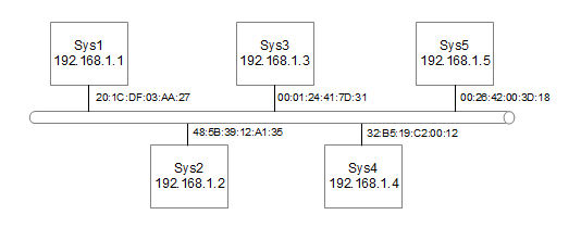
Figure 4: Diagram of Ethernet with MAC addreses
Down at the lower levels the physical ethernet connection does not know anything about IP addressing. The IP addressing occurs at layer 3 which is higher than Layers 1 and 2 that ethernet works at. Instead they use a MAC address which consists of 6 numbers separated by colons. This allows different networking protocols to be carried over ethernet such as SNA (Used by IBM Mainframes) or IPX (formally the default addressing scheme used by Novel Netware).
The MAC address is usually hard coded into the ethernet card and are unique across every device made. This is achieved by allocating a block of addresses to each manufacturer of ethernet devices. Normally the user would not know or care about the value of the MAC address as it is transparent to the user. It is sometimes possible to manually change the MAC address, but this is not advisable unless you have a specific requirement and know what you are doing.
To translate between IP addresses and MAC addresses on the local ethernet the Address Resolution Protocol (ARP) is used.
For example when system Sys1 wants to communicate with another such as Sys4 then the user would use its IP address 192.168.1.4. Now Sys1 needs to convert this address into the MAC address of Sys4. It therefore issues a MAC broadcast to all machines asking for the machine with IP address 192.168.1.4 to reply. Sys4 will reply with it's MAC address 32:B5:19:C2:00:12. Sys1 then adds the IP address and MAC address of Sys4 to its ARP table. Sys4 likewise knows the IP address and MAC address of Sys1 (as Sys1 included it's IP address in the original broadcast) so it adds that to its ARP table. Now in future when ever the systems want to communicate they just lookup the MAC address in the systems ARP table.
If the machine is not located on the same LAN then this requires IP routing which is explained later.
Domain Name System (DNS)
Whilst the IP addressing scheme allows computers to communicate with each other it's not particularly an easy way for people to remember. Which would you find easier to remember www.easytoremember.com or 172.16.35.122 ?
Hostnames have an hierarchical structure. The names read from right to left as though moving down a tree.
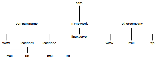
Figure 5: Example DNS tree
Take a few of these examples.
- Starting from the top the first domain below the root is known as the root domain. In this case it is com.
- The next one is the companies or organisations domain for example companyname.
- In large companies they may then split the domain into further subdomains for example by locations. As you look on the tree however not all the machine names have to be included within a subdomain they can end at this level (or indeed at the level above this if necessary). Also for smaller companies (such as "othercompany") they may not have any need to further divide into subdomains.
- Finally the hostname is on the last part of the tree. For example the mail server.
The final name of this computer (known as the fully qualified domain name FQDN) is mail.location1.companyname.com
The responsibility of dividing up all the names below the company name is owned by the end company or organisation. However the organisation domains obviously need to be allocated by a governing body to ensure that two companies don't try and use the same one. This is administered by local organisations dependant upon the top level domain. The top level domain names (TLDN) are allocated by IANA. The primary TLDNs are :
arpa - Used for DNS mapping
com - Commercial
edu - Educational
gov - Government
mil - Military
net - Network support groups or ISPs
org - Other organisations (normally charities)
int - International Organisations
There are also country top level domains that can be used for domains within countries, although note that there is no restriction on being located or working in that country . For example the top level domain for the United Kingdom is uk. Some examples are:
ac.uk - Academic Community (Education)
co.uk - Commercial
gov.uk - Government / Councils
ltd.uk - Limited Companies
org.uk - Other organisations (normally charities)
To explain DNS it's easiest to work through an example DNS request
.If a computer wants to communicate with www.penguintutor.com then it will first contact its local DNS server with an nslookup for that specific site. This will normally be a DNS server provided by their own company or their ISP. Their local DNS server does not know about the existence of the web site. That DNS server may then try asking the root DNS. This DNS does not know anything about the computer in question however it does now about the .com domain and returns details of the DNS servers that owns the domain (in the case of other country top level domains then it will respond with the DNS servers that own that country domain). The local DNS server will then contact one of the DNS servers for the .com domain which will return the DNS servers responsible for the penguintutor.com domain. When the local DNS server then contacts that server is does have the entries for that domain and can provide the specific ip address. In this case it is known as an authoritative answer as it is 100% certain that this is the IP address because it is responsible for that domain. The DNS server can then respond to the requestor with the IP address.
Another way is for one of the intermediate DNS servers to provide a recursive query, whereby it goes and queries another DNS server on behalf of the requesting DNS server. DNS servers do not have to support recursive queries, in which case the initial DNS server will need to perform the lookups itself.
This sounds like a very long process if it has to be carried out for every machine that is to be accessed. If this was the case then the load on the top level DNS servers would be excessive. To speed up the DNS process many DNS machines provide a caching feature where they can store the result of some of the lookups they perform. The names cached can either be for specific hosts (although except for popular sites they will be less likely to have a hit on the cache). Alternatively the DNS will cache the address of another DNS server allowing it to bypass some of the process (for example caching the com DNS would allow the DNS to skip the root query for subsequent .com queries). The use of a DNS cache is so significant that there are even caching-only DNS servers that do not act as a zone of authority for any domain.
If a Domain Name Server is unavailable then it would not be possible to access other machines. Therefore a backup server is configured as a fallback these are called secondary name servers as they can respond to the queries, but do not own the actual entries. The primary name server will push its configuration for any secondary name servers that it has configured as slaves.
In Linux the /etc/resolv.conf file provides details of which DNS servers it should use for DNS lookups.
The DNS process is discussed in RFC 1034 and RFC 1035.
Handling hosts without a DNS server
If you don't have access to a DNS server, or would like to have additional entries not stored on a DNS server then these can be configured directly on the local computer. This can be implemented by adding entries to the /etc/hosts file. The host file is a list of hostnames and their IP addresses which allows them to be directly mapped. This can work for a small organisation or local network but if you had more than a handful of machines it is better to use a local DNS server.
Routing
If two machines are connected together as a point-to-point connection over a physical connection then they can communicate between each other directly. However once we start to communicate to computers on other networks, or over the Internet then routing is needed so that the data reaches the correct destination.
The devices that handle the directing of traffic are known as routers. These routers take an incoming packet and based upon the destination address send them through a different interface to either another router or to the end destination.
For a normal host computer all that is needed to handle the routing of all packets is to define the default gateway. The default gateway is a router directly attached to the same LAN segment as the host that knows how to route the packets on. Then for any address that is not locally held then it forwards the packet to the local router asking it to forward on to its destination. Alternatively for different networks the system could have multiple routes defined for different networks or hosts, or could participate in a dynamic routing protocol.
The router will then forward the packet on directly to the host network or to another router. Whenever a packet passes through a router this is called a hop.
There are three different types of routes. They could be implicit, static or dynamic. Implicit routes are where the configuration of TCP/IP indicates that the address is local to the machine (i.e. on the same physical LAN segment). Static are individually defined (often this will include a default route) and dynamic is where a networking protocol is used to identify the most appropriate route for different connections.
Static Routing
For static routes each entry in the routing table is added by using the route command. This is normally used to connect a host to its networks, but can be used for routers typically in smaller easy to manage networks.
ICMP Redirects
It is possible that when a packet is sent using static routes that it will not neccessarily go the most direct route. For example if there are two routers on the LAN one of which goes directly to the host but the other would have to pass it to the other. This is illustrated below.

Figure 6: ICMP Redirect Example
Here we have Sys1 which is on network 0. There are two routers on the same LAN segment but Sys1 only has a default route pointing at Router 1. When Sys1 wants to communicate with Sys21 it first sends its request to Router1. Router1 realises that it has to forward it on to Router2 and that it would have been easier for Sys1 to have sent it directly there. It forwards the packet onto Router2 so that it reaches Sys21, but then also sends an ICMP redirect message to Sys1. Sys1 then adds a route in its routing table to send any packets for Sys21 to Router2. Then when Sys1 next needs to send a packet to Sys21 it can send it directly to Router2.
The operating system can handle these ICMP redirects or it can ignore them, depending upon the settings.
Dynamic Routing
There are three dynamic routing protocols in general use. These are RIP (Routing Information Protocol), RIP 2 and OSPF (Open Shortest Path First). These work by routers constantly communicating to each other describing the network to each other. RIP uses the hop count (i.e. the number of routers the packet would travel through) to determine which route to send the packet through. OSPF is more sophisticated and allows the network administrator to set metrics to indicate a cost in using a certain route. This allows more expensive links (e.g. dialup connections) and for faster links to be preferred (e.g. those with higher bandwidth or shorter delay times).
These are all interior protocols as they are used within a network. To connect to other networks an exterior protocol is used and this is BGP (Border Gateway Protocol).
Routing Information Protocol (RIP)
RIP is a simple protocol based on distance vectors. It uses a shortest path algorithm to determine the best route to the destination. This is measured in hops which is normally then number of gateways (routers) that are passed through before reaching a destination network. The routing daemon dynamically learns about the network using the RIP protocol and builds its own routing tables.
The line speed, reliability or cost are not taken into account when looking at the shortest link. There is a maximum hop count of 15 using RIP. Any destination over 15 hops away is considered to be an infinite number away and cannot be reached. This is a required feature of the RIP protocol as otherwise it would be possible to get routing loops where the routers through having out of date routes or static routes pass the packet around in a continuous circle.
Whilst suitable for small to medium networks this does not transfer well to a large network, due to its inflexibility and its low hop count.
The updates between routers are sent using UDP on port 520. When a router joins the network it broadcasts requesting for other routers to send their routing tables. Thereafter the router will advertise its tables to its neighbours every 30 seconds. Also if there is an update indicating a change in the network a router will send it immediately (almost).
RIP Version 2 (or RIP 2) provides some enhancements to the RIP protocol. This is documented in RFC 1723. The new features include:
Authentication - only accepts updates when provided with the correct password
Route Tag - Allows a tag value to be added to indicate that a link is external
Subnet Mask - Allows RIP to work in variably subnetted networks
Next Hop - Max RIP more flexible when used in a network with multiple routing protocols (i.e. OSPF and RIP)
Multicasting - Allow routers to multicast updates which is more efficient that using a broadcast.
If using OSPF or RIP 2 on a Linux system then the gated daemon needs to be started. For RIP 2 then the gated daemon is stated with an empty configuration file.
Open Shortest Path First (OSPF)
OSPF is a Link State protocol, therefore uses a a distributed map concept. The network map is a database help by each node and updates and performed by "flooding". All map updates must be secured.
In link state protocols each router is responsible for determining the identity of its neighbours. The router constructs a link state package (LSP) which lists its neighbours and the cost of the link. This is transmitted to all routers which then store the most recent LSP received from each router. The routers then construct a link state packet database from which the routes through the network are calculated.
The routers are normally grouped into areas. The routes in one area will summarise the information to send to the other areas. This limits the size of the link state database and the number of advertisements.
The OSPF protocol provides fast conversion and multiple metrics allowing for throughput, delay, cost and reliability to be taken into consideration. OSPF also allows for multiple paths to a destination providing immediate fallback in the event of a failure. Authorisation is provided for the routers (not available in RIP version 1). There is also no limit on network size with OSPF.
OSPF also allows for load balancing over links. This is more common in routers than in host machines.
Internet Protocol version 6 (IPV6)
So far we've been looking at IP version 4, which is currently the main addressing schemed used on the Internet. The number of remaining IPV4 addresses are running very low and the number of new devices that need IP addresses are increasing rapidly (eg tablets and mobile phones). IPv6 replaces the 32bit addressing scheme with one that is 128 bit long, which should provide as many addresses that will ever be required.
Computers with only an IPv4 address cannot communicate with another that has only an IPv6 address without first going through an intermediate node (proxy). It is however possible to have both an IPv4 and IPv6 address on the same computer using a dual-stack and it is possible to tunnel traffic over a different network.
IPv6 addresses are written in eight groups of four hexadecimal digits with each group seperated by a colon. For example: 2176:03df:1311:21da:0000:0000:33ad:0136. Where the are leading zeros then these can be omitted and one or more groups of consecutive zeros can be replaced by a double colon. Eg. the above can also be written as 2176:3df:1311:21da::33ad:136
Further Reading
RFC Documents
IP Subnet Mask Table Quick Reference
TCP and UDP Port Numbers (/etc/services) Quick Reference
Javier A. Rodriguez
Suscribirse a:
Entradas (Atom)